All the pages on synthesizer design on my website (theover.tripod.com) contain parts that may in various combinations to arrive at working synthesizer software and electronics. The nicest way to make use of this information, and more, is to make an actual, physical synthesizer, a real musical instrument, with keys, controls, display, audio output, samples, drumsounds and sequencer that produces electronic music.
To give an idea of the target machine hardware quality level:
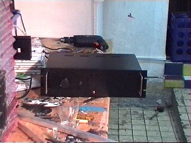
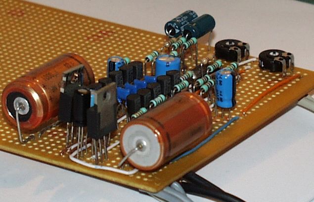
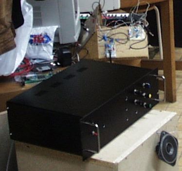
Amplifier in 19 inch enclosure.
which is an amplifier I built.
This report describes such a synthesizer as descripbed above, that actually has been built and works as an instrument. There are still many design choices possible to continue making this prototype into a more diverse, hightech, and complete instrument, but allmost all major elements of a modern electronical music synthesizer / keyboard / workstation (in musical instrument terms) are present to demonstrate in practice what the theory and design knowledge in my pages and in this document is capable of producing.
This report describes the major ideas underlying the current instrument, (which is not yet available in finished enclosure) and is intended to raise its credibility up to the level of demonstrating my capabilities to make an instrument into an actual product, preferably with more technology to add voices, effects and processing making use of the latest computer technology. Also, the implementation details that are essential in synthesis or interface sense receive attention.
The instrument produces sounds that already are up to standard of applicability in music, life or recorded, with various limitations and strong points, and acts as a means of assessing valid and less interesting options in its design in my opinion, and also in more or less objective scientific terms, such as when sound quality, processing power and sonic range are concerned.
First an overview of the synthesizer theory that I've applied is presented in general form, than the microprocessor based prototype is described in reasonable amount of detail, followed by pseudo- and source code of the various system parts of the current implementation. Finally, the sonic results and directions of research and development following from the practical and theoretical materials in this text and the prototype lead to a consistent view on the instrument in terms of what is desirable follow up, and how a product can be expected to be made.
The main parts of an electronical instruments are the input / output parts in physical sense, that is its (piano-type) keyboard, its controls (keys, knobs, analog / digital inputs), display devices (leds, alphanumerical displays), and its sound generators and processors.
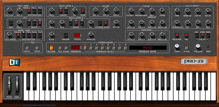
Example a still popular example commercial sythesizer,
the Sequential Circuits (no longer exists) Prophet-5,
first introduced 20 years ago, this picture is from a
software simulation of the real instrument.
The image displays a classical synth with still completely relevant sound and 'interface', and therefore can act as good example, minus that computers have advanced to make more fancy displays possible.
Without paying much attention to all the intrinsities to the whole system, basically, a synhesizer is switched on, than its display displays some message indicating it operates in a certain mode, and is prepared for reproducing a certain sound or 'patch', and awaits the keyboard to be played like a piano or an orgran, that is a sound is produced as soon as one (or more) keys are pressed. In the case of a monophonic synthesizer, only one key can be pressed at the time, that is the electronics can only produce one note at a time (though possibly a complex one), on a polyphonc instrument, chords composed of more than one note sounding simultaneously can be played.
To alter the type of sound, controls can be pushed or twisted, and there are a few 'standard' controllers often present on synthesizers, such as the pitch bend and modulation wheels. The main point of synthesiser is that is creates synthetic tones, that can be programmed on the frontplate of the instrument, for instance notes can be made brighter adjusting a certain knob, or come up slower by turning down another.
On 'traditional' analog synthesizers, actual potmeters like on a stereo set are used that can be turned to change a certain sound characteristic. Computer based, digital instruments can also have knobs, but they have the advantage of being programmable, that is the computer system can be instructed to call up a certain sound, and all knobs are in its memory set to a state corresponding to that sound. When there are physical knobs on such instrument, they somehow must be linked with the settings in the computers memory, for which various methods exist. In short, many modern replaced turning and sliding knobs by push button controls, augmented with a display unit to reflect the changes in all sound paramers. On a small display, on parameter, lets say 'tuning', can be called up at time, which can than be adjusted to the desired value, for instance 'a = 440 Hz' by either typing the value on a numerical keyboard, or by pushing up/down buttons until the desired value is reached.
The disadvantage is far less intuitive and efficient control, and lack of overview of parameters, the advantage is easy programmability, accurateness of the parameter value, and the possibility of accessing very many parameters without many square meters front plate. To know what parameter is adjusted, the display must reference it somehow, for instance by a number (lets say tuning is parameter 32, followed by the deviation in Hz from 442 Hz, say -2), or by displaying the name of a parameter 'tuning', followed by the value, possibly enhanced with some indication of the range of the parameter, its current setting, and its accuracy, for instance a bar graph indicating the minimum (say 439) the maximum (say 448) and the current setting (halfway is 442 Hz).
The main problem with the computer approach is that many parameters may be available, but how can they be found and accessed, that is how do we know what parameters are available, and how can they quickly be located to be adjusted? When all parameters are simply numbered, a list must be available to know which parameter number means what, some synthesizers simply present a list on their front plate for this purpose. When an alphanumerical display is avialable, parameters can be given an understandable name, and some navigation method can be used to 'scroll', or browse through them. When the right parameter is found, its value is made visible, and can be adjusted. A menu structure can be applied to group and hierarchically order large parameter sets, e.g. 'global settings', 'tuning' as opposed to 'sound parameters', 'VCA envelope settings', 'attack', to indicate the rate at which the sound comes up when a key is pressed.
Major considerations are that it is desirable to have knobs for all parameters, with clearly readable function, that is is hard to reconcile with microcomputer storage of parameter values, parameters on such a system must be easy to find and easy to control.
There are a few major architectures for electronical musical instruments: additive synthesis, subtractive synthesis, sampling, and combinations of these.
The following picture shows a research desk for experimenting with various synthesizer elements, as I've built some time ago (I don't have this equipment where I am now), consisting of analog parts.
Analog equipment in development.
Additive synthesis adds together the main parts of sound, for instance an organ has drawbars which each add a certain harmonic to the final sound, a 16' is 'low' harmonic, the 8 foot drawbar adds a single harmonic or sine wave (the smallest contribution to the harmonic structure of a sound possible, a sine wave sounds mostly like a simple flute) an octave higherm, a 4' and 2' again each an octave higher, and all these harmonics added togehter in a certain ratio, visualized for instance like the sliders on a mixer on a row from left to right with the lowest on the left, can create sounds with various characters, for instance 'dull' (only left sliders open) high frequencies (only some right side sliders up), and combinations, for rich sounds good combination of various sliders open.
Clearly, when the slider positions do not change, the sound is static, that is its ends the way it starts when a key is pressed, the character doesn't change dynamically. To make a sound more interesting, it can be made dynamic by addding parts that change over time. On an organ, for instance by adding harmonics that decay over time, so called percussive elements, that start when a key is pressed, and then gradually fade away, to make the sound more interesting, and also more natural, because many natural instruments have decaying components, especially the higher harmonics (principal components of a sound broken down by frequencies), that is they start brighter than they end.
To make more complicated sounds, many harmonics can be added together, including less 'harmonic' ones (e.g. 9 or 13 times the fundamental frequency), each with their own 'envelope', that is time behaviour such as when and how fast it comes up, remains active, and dies out. Certain sounds can effectively and pleasingly be made by adding harmonics or sine waves, for others this method is not simple at all. It can be proven (fourier analysis / synthesis) that any sound can be reproduced be adding the right harmonics in the right ratio at any moment in time. This analysis is a time consuming computer computation that on modern computers can be executed in real time, but is not trivial, and the results are very dependent on the accuracy of the computations. In general, adding hundreds of components togehter can often (re=)create a certain sound, but doing this as sound programmer is hard as 'from scratch' method, because there are so many harmonics, except for sound with straightforward harmonic structure.
Subtractive synthesis is a method where a sound generator makes a noise with a lot of harmonics, which are subsequently filtered, that is only a part of the spectrum passes through a filter. By setting the generators waveform and altering a filters characteristics, few paramers can cover a wide range of sound spectrum changes. Traditional synthesisers rely heavily on this type of synthesis, where the main paramers are generator frequency and waveform (out of three: sawtooth, trangle, square wave), filter cutoff frequency and resonance. The waveforms are chosen because the have clear electronical waveforms: a sawtooth rises regularly from zero to maximum value, and than jumps back to zero, a triangle goes linearly up, and then in straight line down again, and a square wave is either maximal or minimal and jumps between these all the time. Interestingly, the spectrum of a sawtooth contains all harmonics, a square wave only contains odd harmnics, and a triangle is not too far from a sine wave (few harmonics).
The filter is often a 4 pole low-pass filter with resonance, meaning that above the 'cutoff frequency' harmonics are filtered out, with the filter transfer function dropping with 24dB (factor of 1/16) per octave, while a the cutoff frequency, a 'peak' in the filters transfer characteristic is introduced, with a height determined by the 'resonance' parameter. All in all less then a handfull of knobs or parameters to go from very dull to bright sounds, with extra emphasis of the resonance frequency. This method is limited in terms of its spectrm type, but practically is very usefull and 'fat' sounding: many natural instuments have spectra that fall of from certain frequency onward, and by dynamically changing the cutoff frequency, many can be mimiced nice enough. The sound of this type of subtractive synthesis is typically analog synthesizer-like, which after 20 years or so is still in demand because it is pleasing to many ears.
This picture shows an analog filter circuit, a fourth order symmetrical, emitter coupled ladder filter with feedback, based on a Moog filter.
Analog filter implementation with symmetrical supply unit.
Sampling is of a more recent popularity date, and basically consists of making a digital recording of a sound, which is played back at variable rate to reproduce the 'sample' for the various keys on the synthesizer keyboard. Sort of like turning the 'RPM' control on a record player to tune a sound to a certain piano key. Because any sound can be used a starting point, sampling can reproduce anything sonically possible, but the limitations are that one needs to have the sample to start with, i.e. a 'new' sound can not be readily made, samples always sound the same (obviously, but this easily and quickly bores the human musical ear), and when samples are detuned too much they sound donald-duckish, that is they don't sound natural anymore. All these limitations are quite serious and should not be under estimated, the ear very easily picks up the repetition of a certain spectrum, and the resulting sound is quite 'dead', while detuning for instance piano tones for more than a few keys already sounds quite unnatural.
On the other hand, samples can be anything, which means that if they can be applied as little pieces of tape, which can be produced and played back at will, they are versatile building blocks for sounds. When two samples are combined (in parallel) the detuning between them makes for richer sounds because of the beating patterns arising from the mix, just like traditional synthesizer generator waveforms are combined, and then they obviously are capable of producing more varied results, assuming the right samples are somehow available.
Samples can also be played in sequence, i.e. after eachother, for instance to reflect changes in a sound, though obviously the splicing point must be musically a pleasing effect, of must be gradual, which is harder to achieve. Because a sample has limited length, it is customary in samplers to 'loop' a sample from the moment it reaches the end of the virtual piece of tape, that is it winds back to a certain point when it reaches the end, preferably in a way that doesn't sound glitchy, though it is almost always audible that the loop is active.
A wave-sample is a short sample, consisting of only one waveform, the size of a funcdamental of a sound, that is such that the the lowest frequency in a sound just fits the sample length. Instead of a sawtooth, triangle or square wave, such a wavesample can be used as oscilator equivalent by simply looping it, which is an interesting improvement to a traditional synthesizers' generators. Practically, these analog synthesizers have generators that are voltage controlled, that is a voltage determines their frequency, and they respond instantaneously to voltage changes. To achieve the equivalent with wave samples is not trivial, and usually not available in digital synthesizers.
There are at least two more well knows types of sound synthesis, the most well known is FM synthesis which in the form of Yamaha instruments is well known for its capabilities of generating sounds with great clearity and harmonic richness. This form of synthesis consists of sine wave oscilators modulating eachother in frequency, with time varying modulation index, that is the amount of frequency modulation varies by an envelope generator. Various algorithms consisting of for instance 6 oscilators (for the famous DX-7) in various constellations generate sounds built from additive and frequency modulated components. This requires various (sine) oscilators that can be modulated with audio rate, and is computationally not easy, that is a computer most be quite fast to make all this happen when it is done digitally. The sonic results can be quite varied and high quality, but it is not at all an easy synthesis method to program intuitively.
The is 'physical modeling', which is a recent method to do computer simulations based on an instruments' physical properties, that is a computer program simulates the propagation of sound waves in a string or air column and the body of an instrument, to arrive at more accurate physical instrument sound emulations. The method works well for simple enough instruments, such as wind instruments, though already here fast Digital Signal Processors are needed to do these simulations in real time. For more complicated instruments interesting research is going on, commercial instruments are not yet available to do for instance physically based piano sounds based on wood type, harp geometry and string material...
I've programmed physical modeling based string simulator software, that already is quite advanced at generating CD quality samples of virtual string-type instruments, with a few hundred' order waveguide computation on fast enough pentiums. This software is avialable via my web site at http://theover.tripod.com, it is written in C, with real time tcp/ip simulator to tcl/tk simulation time user interface with dynamic string shape display. A few versions, and some example wav files are in my later diary pages.
The simulator has non-homogeneous string ends, non-linear string coupling ove the 'cam', and a distorting amplifier feedback simulation as integral part of the vibrating string algorithm, i.e. as physically modelled effect. This is a major sound research direction for appying in a synth with significant DSP horse power, proven already to generate beatifull, powerfull and interesting sounds.
As new member of Fourier-type of synthesis, the current synth sound/wave sample generator software enables localized harmonics not on a per fundamental sample length basis, and not just on an interpolation basis, but inside a wave sample, with sinc or gaussian based envelope, over a very short time interval. Call it a length-tuned minimal wavelett to add harmonics at exact times instead of the crude and arbitrary fourier synthesis based on integer harmonic or fundamental length envelope intervals. The relevancy soundwise can be made credible by considering the ear-hairs in the human ear picking up harmonics (a slort, gradual packet of the minimal amount necessary to 'suggest' or make perceive a certain harmonic. Practically, the technique works for three reasons: it generates interesting and strong sounds, it has shown to break down fourier harmonic synthesis a lot more refined than standard methods, and make difference, and audio wise it generates samples which are more versatile than without attention for the localisation of harmonics and their interrelation, for instance by taking the simple example of a combination of only two oscilators with detuning, as often is used in synthesizers.
The idea of the smooth pulse within a wave sample acting as an envelope for a single harmonic is similar to a pulse waveform added to a sample, with possibly the same 'nasal' qualities, but it offers other possibilities as well, it adds the harmonic to the spectrum without making the sine wave of that harmonic sample-long. Now consider the beating patterns that result from detuned samples with similar harmonic content (including phases). When the phase difference between the samples is 0 degrees, all harmonics are added and basically the samples are reproduced at +6 dB (i.e. twice as loud) as a single oscilator. No lets say the phase difference is 180 degrees: then all even harmonics cancel out, because of their symmetry: the second half of a sine wave is exactly inverted compared with the first half. There is no way out of this, that is in the beating patterns there is a complete daming of all even harmonics at some point, no matter what their amplitude is. By phase shifting, it is possible to make them damp out at different points in time, which makes their interaction more interesting. For instance in the case of detuned organ notes, the vibrations in amplitute (and after non-linear mixing also in frequency) become more varied when the harmonics (such as 1st, 2d, 3d, 5th, 7th, 8th, 9th, 12th, 16th) are mixed with a phase offset. Still, the beating patterns are regular (they can be computed), and have the same envelope for each harmonic as a result, except with different time scale. When a harmonic is present in only a part of the (repeated) wave sample, the interference between the two oscilators for that harmonic has a different quality, amplification and/or damping take place when the pulsed harmonics 'come together', because the phase diffence slowly makes the locations where they occur have equal phases and then move away again. The result is worth it: interesting harmonics can be combined, and have sudden amplitude changes when two oscilators are combined. The sound is good enough to use as basis for good synthesized sounds, with peaks that are actually good enough to be presentable straight away from keyboard-ish imitations and squeeks
All synthesis method can in principle be implemented either electronically or digitally, though electronical sampling is rare. Traditional analog synthesizers have regained popularity over their seemingly more capable digital counterparts, mainly because of what is best described as 'warmth' and 'fatness' and even the fact that they actually have knobs that can be turned instead of a computer keyboard. This is not just hype, there are objective reasons why their sound is pleasing and more capable of certain characteristics than most digital algorithms. Filters are a main factor, as well as the fact that sampling theory is not without complication, and one can nor sin against the implicit complexities of its applicatation without paying a penalty in sound quality. Samples are the basis of digital synthesizers, in one form or another, and their application requires application of knowledge about sampling theory, including the transformation of circuit diagram based electronical circtuits to their digital counterparts. In fact, it requires a lot of attention to make good simulations in computer form of analog circuitry, especially when such circuitry is designed to sound good and therefore is far from straightforward and signal-path-wise sensitive to small variations.
The first target computer architecture is limited to a (not too slow) mircroprocessor based architecture, which does both the interfacing and sound generator processing, possibly exteded with analog generator, filters, and possibly with specific added hardware for wave sequencing and / or phase incrementing (for playing back samples, see furhter on). That means emphasis is on making implementations of all interesting parts of synthesizer parts that can on faster architectues be made more elaborate, accurate, polyphonic, or efficient.
The limitations of the current implementations are that I've focussed on strictly the microprocessor + IO and fast digital to analog converter, but with the addition of externally generated data being fed directly into memory. Basically, polyphony is limited, samples are 8 bit, memory is small, and digital processing is not including filtering. Interestingly, within these limtations interesting sounds can be generated, and all parts of a more extensive design can be tested, except for complicated real time signal processing and large data sets. Since a sampler design in the megabyte sample range is not the objective, and an external PC is available to prepare compuations, design choices in the synthesis domain are not too guided by limited resources, though focussing on the bare essence is clearly stimulated. It is most natural to see the design as an equivalent of a traditional syntheiser with many digital parts, and partial non-real time programming.
The relevance of the prototype is that it is capable of either being completely to the point addition to an analog or special purpose digital architecture, and that as a self contained digital instrument it is powerfull enough to show most properties of a design based on powerfull processors. On top of this, the interfacing capabilities can immedeately be used in a product instrument, possibly as addition to a DSP based system.
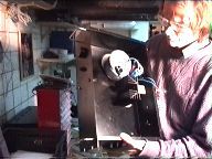
Early monitor speaker system with amplifier + analog (Moog
type) of filter unit and control knob filled front pannel on top.
In the back the little keyboard (with analog VCO's on breadboard)
is visible.
A Z80 running at 10 to 35 megaherz with keyboard (both computer and synthesizer), display, DMA, and digital to analog interface is presented, along with a development system consisting of a x86 based (cross) assembler and C compiler, and programmer link based on a PC printer port.
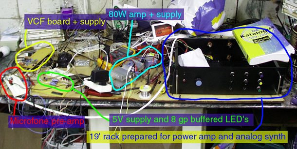
The following image shows main parts of the system:
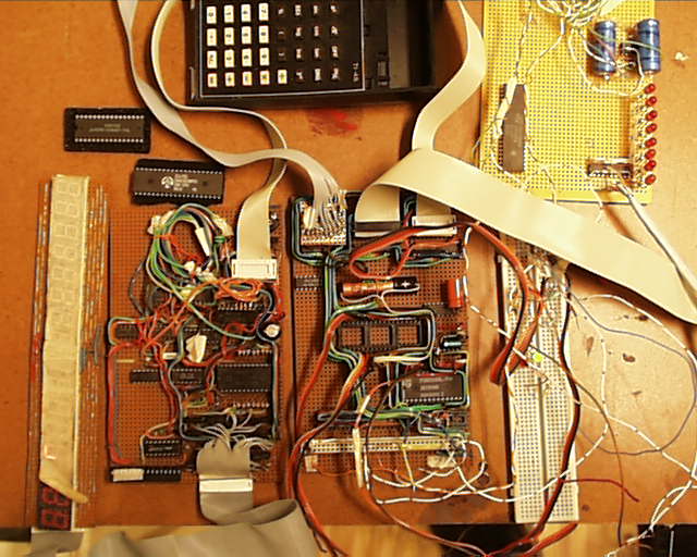
The display unit, display card, bare CPU card,
one additional breadboard, calculator keyboard (used sidewise),
supply / bus monitor card.
Missing from the picure: the DMA unit breadboard, and the memory selector, DMA controller, Digital to Analog converter eurocard.
The Z80 is a recent 40 pin DIL CMOS processor, with a CMOS memory, currently 8 kBytes (128 k available), of which 4k write protected, with battery backup. Memory is addressed per bank of 16 K of which the second is divided in 16 pages for IO purposes, where the various 74HC573 buffers are mapped for input and output. The display unit consists of 16 7 segment led displays (with decimal point), which are addressed by the high nibble of memory page mapped buffer, and driven in multiplexed form by another memory mapped buffer. Transistors with current limiting and a 4 tro 16 line decoder are on the display print, which is band cable connected to the CPU board.
A calculator keyboard with 40 (forty) keys arraged as 5 rows of 8 colomns is available as alphanumerical keyboard (stickers for letters and numbers), its 5 rows are driven by a memory mapped buffer, with diode decoupling of the rows, the colums are read by another memory mapped buffer, with pull down resistors on its inputs.
A small baby piano keyboard (not in the picture) has been fitted with bandcable to be scannable for two octaves, arranged as 3 rows of 8 bit colums, and can be plugged into the keyboard connector te use the remaining 3 bits of the keyboard rows, also over diodes. The cable has a contra plug to connect the calculator keyboard to. The calculator keyboard can also be used alone in the CPU card connector, it then has high impedance pull downs, for low power operation, the piano keyboard has low impedance pull downs (1Kohm) for low disturbance sensitivity (unshielded bandcable is used) and fast key scan pattern settling times, which is needed for fast key scan routines.
The clock generator is a 74HC14 (schmitt trigger) based RC or cristal oscillator, which can be clocked by hand, too. An RC/HC14 based reset circuit is provided that is designed to preserve memory contents on startup and power down (though the current, not too recent, slow CMOS cpu is not to clean in its responses in this department, 2 others were), for all kinds of power cycling, before and after stabalizer switches, pulling the transformer plug, and short circuits.
Another memory mapped 74HC573 (8 bit latch with 3 state bus driver output) drives a precision resistor network to do very fast digital to analog conversion, which currently is immedeately few to a power amp, without any processing.
A set of 3 bi-directional 8 bit bus buffers (HC 373) for the complete data and address bus is available to do DMA access and off-board bus buffering, under control of random logic based selection circuitry, including memory preserving tri-state bus control (MREQ, RD, WD) signal driving when DMA mode is acknowledged.
A set of 3 times 4 bit resettable DMA counters upper one programmable), linked with manual DMA request / RUN buttons are connected to the PC printer interface 'strobe' signal, while another HC573 data bus buffer feeds the printer interface data lines to the cmos memory in DMA mode. The memory write signal is applied when the strobe signal is high through the DMA mode control signal tristate buffer. A wire in the DMA circuit breadboard makes selects the higher or lower 4KByte, the lower is protected by a write protect switch. The rest of the circuitry, outside the DMA unit, is hard wired is on general purpose 1/10 inch board with long copper lines, and distributed over mainly 4 eurocards conencted with flat cables: a cpu/memory/io card, a control/DAC card, a display card, and a supply/led monitor card.
Note that the current system does not use its interrupting facilities, mainly because this complicates sample timing accuracy and adds overhead, and isn't realy needed for this type of system as I've applied it. Nothing is against adding an interupt signal, and using double buffering to the DA converter driven by the interupt signal, the infrastructure is available, and the DA converter input is breadboard compatible connector - connected with the buffered databus, which is available for breadboard connectivity over standard 1/10 inch badcable connection cables, of which I've made more than a few.
It spawned serious library research on EMI, and in the end I found QUITE a lot is indeed (as I expected) to be said about it, including about 3 full pages of TYPES of tests and corresponing standards in EEC and US. I suspect >4kV surges...
When I'll be into sampling, I'l do some measurement, always a good basis, but not the current emphasis. First the synth of the ground.
The microprocessor system needs keyboard and display routines, besides it synthesis and sample generator software. These are sophisticated enough, including cursor based ASCII string rendering on the display and full alphanum capabilities of the software debounced calculator keyboard (though currently not QUERTY).
The interupts are disabled at startup, and the only entry point for all software is 0x0000. The stack is located in upper memory at 01ffe downward, 0x000 through 0x0fff is normally write protected for system routines, string segment and synth software, 0x1000-0x1fff is available for variables, test dynamic routines, samples and display buffer memory. This limitation can be lifted by using an already available medium fast 128k CMOS memory backed memory, not soldered in the current system.
The io memory map with address shortcuts is:
DISD  0x2400  Display Data
DISA  0x2600  Display Address
KEYD  0x2800  Keyboard Data
KEYA  0x2A00  Keyboard Address
DAC   0x2C00  Digital to Analog Converter
All these registers are 8 bit, thought the display address buffer only uses the upper nibble. It must be written a few times on higher clock frequencies, because the older CMOS demultiplexer buffer isn't up to full speed clock pulses.
The display software can be simple:
	ld	a,16*display_number	; which of the 0..15 display
	ld	(DISA),a
	ld	a,7seg+dot_bitpattern	; see bit order note
	ld	(DISD),a
where the bit order is upper right segment, lower right, bottom, lower left, upper left, upper, middle, decimal dot, from LSB to MSB.
An ascii converion table is available to make all alphanumerical characters a-z and 0-9 available as lookup, which also contains the decimals and a-f in the lower 16 locations to facilitate hex display. A few display update routines are madem to basically render a 16 long ascii string into the display and continuously refresh.
Even an additional blinking cursor routine is available, in combination with a keyscan routine.
In short, this routine isn't prepared for during synthesis use, it is not written as a thread with equal execution time update call possibilities, it just calls a delay routine to waste time during scanning, interleaved with the keyscan routine, and a test for 'special keys' to invoke program parts. This is a technical possibility though, that would make the display continue during sample playback for instance.
Any asci string can be rendered in the display buffer at any location, and conversion routines are available for single byte hex and decimal muber converions to cursor location.
Example of decimal display routine:
; put a decimal value on the display

.disdec:
	push	hl
	push	de
	push	bc		; save regs
	ld	hl,#.discs+15-3	; adress of display buffer, last
				; character, minus 3
	ld	e,a		; assume the value to convert is in A
	and	#0x80		; check if negative
	ld	a,e
	jp	z,.huns2	; determine 100 count
	cp	#200
	jp	m,.huns2
	sub	#200
	ld	b,a
	ld	a,#2
	ld	(hl),a		; put on display (in buffer that is)
	inc	hl		; point to next
	ld	a,b
	jp	.tens3
.huns2:	ld	b,#100		; rest of the hundreds
	ld	c,#0
.hunsl:	cp	b
	jp	m,.tens
	sub	#100
	inc	c
	jp	.hunsl
.tens:	ld	b,a
	ld	a,c
	ld	(hl),a
	inc	hl
	ld	a,b
.tens3:	ld	c,#0
	ld	b,#10
.tensl:	cp	b
	jp	m,.ones
	sub	#10		; count the factors of 10
	inc	c
	jp	.tensl
.ones:  ld	b,a
	ld	a,c
	ld	(hl),a
	inc	hl
	ld 	a,b
	ld	(hl),a		; put the ones in the last location
				; the conversion table puts the
				; digits in place (0-9)
	pop	bc		; restore regs
	pop	de
	pop	hl
	ret			; end of display decimal
Basically the alphanum keyboard scan routines slowly scan the keyboard and produce a character code from 0 through 39 for a detected key press or 255 for no key press. The main one is called repeatedly, always returns quickly, and return a key match for the lowest key pressed (number wise) only once for each time a ke is pressed.
An alternative is to simply red one row of keys:
	ld	a,2exp(row_nr)	; which row (5th is lowest on 90
				; degree turned keyboard)
	ld	(KEYA),a;
	call	.delay
;	.
;	.
	ld	a,(KEYD)	; get key pattern
The piano keyboard has three keyboard ranges, from the lowest c sharp on the active 2 octaves, to the highest c, available as row 0b00100000 through 0b1000000, with LSBit is lowest key in the scan pattern.
In the display update / key type / cursor routine, a hook is made for calling a piece of code based on a key with a certain number.
Three major tests based on these routines have been written and verified to work. First, a parameter edit routine, basically, a byte is converted to a hex value, put on a fixed display position, followed by the same value in decimal converted form. The keyboard is read, and when a key is pressed the value is incremented once (in debounced fashion, of course).
Second, this has been combined with showing menu texts, based on 5 keypresses. Each key displays its' own text on the left part of display, for instance 'command', 'run synth' and 'help'. The display gracefully changes text and continues to display the parameter values when keys are pressed.
Thirdly, a calculator type of program can be selected by pressing a menu key. In this basic version, the invisible cursor runs over 6 display locations, where the characters types are displayed. These characters are interpreted as two 3 digit decimal numbers from 0 to 255 (one byte), which are added together, and the result is shown as 3 digit decimal result on the rigth side of the display. Also this works fine, except of course that the sum may overflow.
To get characters on the display, a conversion table is available to arrive at readable alphanums on the 7 seg display. Below a part of the table, and a string put routine, also as example of what the assembler can do.
	.globl  .reset			; global variable / label

	.module chars			; a module defintion
	.area   DISLIB  (ABS,OVR)	; absolute overlay mode
					; since we know where all goes
	.globl  .strp,.cbase		; pointer to string list, and the
					; conversion table base address
	.globl  .puts			; make routine available to
					; other modules

	.org    0x0100
.cbase:
			; some unneeded stuff omitted from this listing
	.=.cbase+#0
.digts: .db     0b00111111     ; a 0 on led display
	.db     0b00000011     ;   1
	.db     0b01101101     ;   2
	.db     0b01100111     ;   3
					; ... etc
	.=.cbase+#65
.charc:					; for those interested: the letters
	.db     0b01111011      ;a
	.db     0b01011110      ;b
	.db     0b00111100      ;c
	.db     0b01001111      ;d
	.db     0b01111100      ;e
	.db     0b01111000      ;f
	.db     0b00111110      ;g
	.db     0b01011011      ;h
	.db     0b00000010      ;i
	.db     0b00000111      ;j
	.db     0b01011000      ;k
	.db     0b00011100      ;l
	.db     0b00111011      ;m
	.db     0b01001010      ;n
	.db     0b01001110      ;o
	.db     0b01111001      ;p
	.db     0b01100011      ;q
	.db     0b01001000      ;r
	.db     0b01010110      ;s
	.db     0b01011100      ;t
	.db     0b00001110      ;u
	.db     0b00011111      ;v
	.db     0b01011111      ;w
	.db     0b00001010      ;x
	.db     0b01010111      ;y
	.db     0b00101101      ;z

					; ...

	.=.cbase+#126
	.db	0b00000100	; cursor symbol
	.db	0

	.even

; The idea here is that there is some array with a set of strings
; that can be put on the display by calling this routine with
; the number of the string in the A register.

.puts:  push    hl		; save registers
	push    de
	push    bc
	ld	hl,#.strp
	add	a		; A=A*2, so 127 strings addressable,
	add     a,l		; A offsets in string pointer array.
	ld      l,a		; address string pointer (mind page bound.)
	ld      l,(hl)		; get right one
	ld      de,#.discs
	ld      c,#16
.putsl: ld      a,(hl)		; copy string
	and     a
	jp      z,.putsr
	ld      (de),a
	dec     c
	jp      z,.putsr
	inc     hl
	inc     de
	jp      .putsl
.putsr: pop     bc		; restore registers
	pop     de
	pop     hl
	ret			; end of put string routine
As an example of how to use this idea:
.strp:  .dw     #.strstart, #.strcmem, #.strccom, #.strcsyn
	.dw	#.strchlp, #.str1, #.str2, #0
.strstart:
	.asciz  '1 to 4 and enter'	; 0
.strcmem:
	.asciz  ' examine memory '	; 1
.strccom:
	.asciz	'  command line  '	; 2
.strcsyn:
	.asciz	'run  synthesizer'
.strchlp:
	.asciz	'    h e l p     '
.str1:  .asciz  'input detune'
.str2:  .asciz  ' SYNTHESIZER ON '
Now simply laod a with the number of the string and call puts to load the display buffer.
The following listing displays strings, and numbers on the display, and form a test containing all elements needed in various display tasks: number converion, cursor based display addressing, menu display, parameter increment on display, key response combined with display refresh and calling program sections under key control.
Won't get a prize in acedemics, but all these tasks work, mind that the keyboard and string modules must be available to for this to work, and that the calculator and synth module are called, and therefore must also be available.
;
;       test the display routines
;

DISA    = 0x2600        ; IO addresses
DISD    = 0x2400
KEYA    = 0x2a00
KEYD    = 0x2800
DAC     = 0x2c00
	.globl  DISA,DISD,KEYA,KEYD,DAC

	.module disp1
	.globl	.begin
	.globl  .reset, .discs, .cntr, .keyc, .keyl, .keycur, .curs
	.globl	.delptr, .dlya, .dlyac, .dlybc, .count, .ondis, .val

.reset: ld      sp,#0x1ffe
	im      0
	di
	jp	.menus
       .=.reset+#0x0010
.begin: ld      de,#DISD
	ld      a,#0x10
	ld      (#KEYA),a
	ld      hl,#0
	ld      (#.dlyac),hl
	ld      (#.dlybc),hl
	xor	a
	ld	(.keyl),a
;	ld      a,#3
;	call    .puts
	call	.clrdis
.loop1: ld      bc,#0x0000
	call    .typec		; type character routine
	ld	a,(.keyl)	; returns last character in .keyl
	cp	#2
	call	z,.synth	; second alphanum key? call synth routine
.lop2b: call    .count		; for each keypress increment an on display
				; hex/decimal byte counter
	ld      a,(.cntr+1)
	call	.arith		; do some arithmetic stuff
.loop2:
	ld      hl,#.discs	; point to display characters
	add     hl,bc
	xor     a
	ld      (de),a
	ld      a,c		; c is the display number (0..15)
	add     a
	add     a
	add     a
	add     a		; shift left 4 times
	ld      (DISA),a
	ld      (DISA),a	; make right display active
	ld      a,(hl)
;       ld      hl,#.digts
	ld      hl,#.cbase	; point to character table base
	add     a,l
	ld      l,a
	ld      a,h
	adc     a,#0
	ld      h,a
	ld      a,(hl)		; lookup character
	ld      (de),a
	call    .dlya		; delay
	inc     bc
	ld      a,#16
	cp      c		; last display position?
	jp      nz,.loop2
	jp      .loop1

.dlya:  push    hl		; delay routine a with fixed length
	push    de
	ld      hl,(.dlyac)
	ld      de,(.dlyam)
.dlyal: inc     hl
	call    .dlyb		; call another delay routine: b
	ld      a,h
	cp      d
	jp      nz,.dlyal
	ld      a,l
	cp      e
	jp      nz,.dlyal
	ld      hl,#0
.dlyad: ;ld     (.dlyac),hl
	pop     de
	pop     hl
	ret

.dlyb:  push    hl		; delay routine b with fixed length
	push    de
	ld      hl,(.dlybc)
	ld      de,(.dlybm)
.dlybl: inc     hl
	ld      a,h
	cp      d
	jp      nz,.dlybl
	ld      a,l
	cp      e
	jp      nz,.dlybl
	ld      hl,#0
.dlybd: ;ld     (.dlybc),hl
	pop     de
	pop     hl
	ret

.count: push    hl		; add a fixed value to a 2 byte counter
	push    de
	ld      hl,(.cntr)
	ld      de,(.cntri)
;       .byte   0x34    ; inc (hl)
;       inc     hl
	add     hl,de
	ld      (.cntr),hl
	ld      a,h
	pop     de
	pop     hl
	ret

.ondis: push    hl		; put the value in A on the display
	push    de		; in hex form, at cursor position.
	ld      de,(#.curs)	; check where global cursor points at
	ld      d,#0
	ld      hl,#.discs
	add     hl,de
	ld      e,a
	and     a,#0xf0
	srl     a
	srl     a
	srl     a
	srl     a
;       ld      a,#0x05     ; for test
	ld      (hl),a
	inc	hl
	ld      a,e
	and     #0x0f
	ld      (hl),a
	ld      hl,#.discs
	ld      a,(.keycur)
	inc	a
	and	#0x0f
	add     l
	ld      l,a
	ld      a,(.cntr+1)
	and	#1
	add	a,#126
	ld      (hl),a
	pop     de
	pop     hl
;       ld      (.discs+8),a    ; for testing
	ret


.cntr   = 0x1e00
.dlyac  = 0x1e02
.dlybc  = 0x1e04
.disrw  = 0x1e10
.discs  = 0x1e20
.curs   = 0x1e40
.keyc   = 0x1e42
.keyl   = 0x1e44
.keycur = 0x1e46
.delptr	= 0x1e48
.val	= 0x1e4a
.chars  = .cbase ; 0x0100

	.even
	.dw     -1
.cntri: .dw     12	; counter increment per display refresh
.dlyam: .dw     3	; delay count max
.dlybm: .dw     30

	.globl  .strp                   ;.str1, .str2
This code return clean key number codes for each key pressed.
; ; Keyboard routines ; ; vars: .keyc .keyl: column, last key .module KEYBOARD .area keyboard (ABS,OVR) .globl .typec, .keybd .org 0x0200 ; third page in mem, ; for debugging ease .typec: push hl push de ld a,(KEYD) ld l,a ; key pattern ld a,(#.keyc) ld e,a ; key column # inc a and #7 ld (#.keyc),a ; new col# in store ld h,a ld a,#1 inc h .typ2: dec h jp z,.typ1 add a,a jp .typ2 .typ1: ld (KEYA),a ; set new scan address ; ; l=read key scan ld h,#1 ; shifting 1 ld d,#0 ; counter .typ5: ld a,l and h jp nz,.typ4 inc d sla h jp nz,.typ5 ; nothing pressed ld a,#7 cp e jp nz,.typ7a ld a,#0xff ; end of scan: no key ld (#.keyl),a jp .typ7 ; then 0xFF as key code .typ7a: ld a,#0xff jp .typ7 .typ4: ld a,e ; keycode = 8*colum+row of first hit add a add a add a add d ld l,a ; ld (#.keyl),a ; as soon as pressed: store and rescan xor a ld (#.keyc),a inc a ld (KEYA),a ; the columns are addressed slow here ; that is the keyboard gets a lot of ; time to respond before the row ; is read. ld a,(#.keyl) cp l ld a,#0xff jp z,.typ7 ;same key: don't repeat on screen ld a,l .typ8: ld (#.keyl),a .typ9: ld a,(#.keycur) ; cursor inc a and #0x0f ld (#.keycur),a ld de,#.discs add a,e ; make pointer ld e,a ; assume not at page boundary ld a,l ld a,#39 sub l ld l,a ; invert coding (lower left=0, sidewise) ; cp 39 ;-- clear display ; call z,.enter and #0xf0 ld a,l jp z,.typhx add #49+6 ; ld (#.discs),a ; test .typhx: ld (de),a .typ7: pop de pop hl ret .keybd: ;push hl ld a,(#KEYD) and a,#0x7 jp z,.keyr ; call .puts ld a,(.cntr+1) and a,#0x07 ld a,(#.curs) jr nz,.keyb inc a .keyb: and a,#0x0f srl a srl a srl a srl a ld a,#14 ld (#.curs),a ; ld (#.discs+9),a ; should be curs .keyr: ;pop hl ret
Lots of stuff here for various testing purposes, these routines are straight from the working prototype interface software with some edits, that is they work in practice, but are not shown primarily for educational value.
Mainly two programs have been tested and used to 'play' with: a wavesample player, and a sample player, the former with delay unit included, and with user interface prototype, including a simple calculator routine.
Already 20 years ago, then on a trs80 clone at barely 2 MHz, I thought about sample playing, and 'invented' (though I'm sure the principle existed, I did invent it myself, which at the time gave me great satisfaction) a phase inrementing routine for the Z80. It was just fast enough to make sounds with, and in 2 variations it is used here.
A register pair addition is used to increment the phase, than a pointer is constructed with the most significant part of the result, a sample is looked up from a sample list, and the value put on the DA converter.
The two alternatives currently programmed differ in the pointer formation, and the type of addition in the phase incrementor. The first variation assumes a 256 long sample table, uses on byte as 'behind the comma', or increment value, and can in principle run over samples with larger than increment as it is (though I don't do that now).
The second uses the whole 2 byte phase value as fraction, and only advances a pointer when the 2 byte phase increment addition produces a carry. Then the pointer offset is also a two byte value, allowing sample length up to full memory size. The second version wraps back the sample pointer from a selectable loop point, assuming a 256 sample long fundamental equivalent. The whole routine is fixed execution length for two oscilators, based on the alternate register sets, and runs as supersonic sample frequency.
The first (wave) sample player has the option of using a delay effect on one of the oscilators, with a delay length of currently 2Ksample.
A sequencer/arpegiator has been added to the second sample player. On the alphanum keyboard there is a sequence-record button, a sequence-stop button, and a sequence-playback button. When the sequencer is enabled in the assembly source code, the sample player becomes multiple trigger, single short kind: when a key is pressed the whole sample is played without local loop. When the key is pressed for longer than the sample duration, the whole sample is played again, in sequence stop or sequence record mode
In sequence record mode, the display shows the current key being played in the display number curresponding with one of the 16 sequence steps, every time a new key is pressed, the display position advances by one, and the keycode is shown in binary form. When the sequence-playback key is pressed, the display cycles through the sequencer steps, playing the notes stored in each location of the sequence with a fixed duration, i.e. independent of sample length or note being played. The sequence rate is currently fixed at assembly time. Sequencing stops when the sequence-stop button on the alphanum keyboard is pressed.
An arpegiating option has been added, it adds a note an octave lower alternated with the original half the time to beef up the sequence.
;
;       Synth module
;
;       oscilators
;       delay with feedback
;

.sp     = 0x1e80        ; variable area (under stack in highmem,
			;                see also disp1.asm)
.s1     = 0x11          ; sample 1 page addresses
.s2     = 0x12
.dl     = 0x14		; delay line base page address
.dll    = 2*0x0400	; delay line length (2k)
.itab1  = 0x08		; keycode to phase increment table page for OSC I
.itab2  = 0x09
.synv	= 0x0c		; page for synth variables

	.module SYNTH
	.area   osc     (ABS,OVR)
	.globl  .synth

	.org    0x0400
.synth:	push    hl
	push    de
	push    bc
	ld      a,#0x10
	ld      (KEYA),a	; activate bottom alphanum key column
	ld      b,#0
	exx
	ld      b,#0
	exx
.synl1: ld      d,#.itab1
;       ld      a,(#.note1)
	ld      a,(KEYD)	; get key scan pattern
	ld      e,a
	ld      a,(de)          ; get phase increment from table
	ld      c,a
			;;;;;;; sample play loop
	add     hl,bc 	; 11	;;;;; phase increment
	ld      e,h	;  4	; high byte current phase to pointer low byte
	ld      d,#.s1	;  7	; pointer high byte = sample page
	ld      a,(de)	;  7	; read sample
			; ---+	;
			; 29 cylces per sample, -7 (preload) , so 22+store
			;;;;;;;
;	call    .delay          ; do reverb
	ld      (DAC),a 	; output osc1 sampel to DA converter
;	call	.delay
.synl2: exx			; same for OSC II with alternate reg. set
	ld      d,#.itab2
;       ld      a,(#.note1)
	ld      a,(KEYD)
	cp      #0x82           ; back to interface sw
	jr      z,.synret
	ld      e,a
	ld      a,(de)          ; get incr
	ld      c,a
	add     hl,bc
	ld      e,h
	ld      d,#.s2
	ld      a,(de)          ; read sample
	call    .delay          ; do reverb
	ld      (DAC),a ; output osc1
;	call	.delay
	exx
	jp      .synl1

.synret:
	exx
	pop     bc
	pop     de
	pop     hl
	ret

.delay: push    hl		; cyclic delay routine
	push	de
	push    af
	ld      hl,(.delptr)    ; pointer in delay memory
	inc     hl
	ld      a,#0x07         ; limit range to 8 pages (=2kb)
	and     h
	ld      h,a
	ld      (.delptr),hl    ; store next value
	add     a,#.dl          ; add page base
	ld      h,a
	ld      a,(hl)          ; read previous val from buffer
	ld      (DAC),a         ; sound
	srl     a               ; sample / 4
	srl     a
;	ld	e,a
;	srl	a		; add a 1/8 sample amplitude
;	add	e
	ld      (hl),a          ; feedback
	pop     af              ; get current osc output
	add     a,(hl)
	ld      (hl),a          ; store new sample in buffer
	pop	de
	pop     hl
	ret

;;;; streaming synth in builtup: not a finished routine (unlike all others)
.synt8:	push	hl
	push	de
	push	bc
	ld	hl,#0		prepare stack 4*4 samples*2 bytes,
				highest is sample.
	ld	(.synv+0),sp
	add	hl,bc	; 11
	ld	e,h	;  4
	ld	a,(de)	;  7
	push	af	; 11
			; total: 22
	add	hl,bc
	ld	e,h
	ld	a,(de)
	push	af

	add	hl,bc
	ld	e,h
	ld	a,(de)
	push	af

	add	hl,bc
	ld	e,h
	ld	a,(de)
	push	af

	jr	.synt8
	pop	bc
	pop	de
	popd	hl
	ret
These routines read a sample at variable rate, play it through the digital to analog converter, and loop at the last sample page, as long as a key is pressed on the top two octaves of the baby piano keyboard.
;
;	Sample player
;
; 	Monophonic, II osc. just to test wav player idea ++

; This sample player proto takes samples of
; any length, plays them from the start at a
; keypress, and stops at key release.

DISA    = 0x2600        ; IO addresses
DISD    = 0x2400
KEYA    = 0x2a00
KEYD    = 0x2800
DAC     = 0x2c00
	.globl  DISA,DISD,KEYA,KEYD,DAC

	.module SAMP
	.area	samp	(ABS,OVR)	; now takes zero page and further
	.globl	.begin

.sbase	= 0x1000	; ptr to sample base adress
.sptr	= 0x1e10	; variable: sample ptr
.send	= 0x1e12	; var: sample end ptr
.key	= 0x1e14	; var: key pressed
.pinc	= 0x1e16	; var: phase increment
.pinc1	= 0x1e18
.pinc2	= 0x1e20
.pptrl	= 0x1e18	; var: phase ptr low word
.pptrh	= 0x1e1A	; var: phase ptr high word
.ppmax	= 0x1e1C	; var: phase ptr max phase (msw)
; .notes1	= 0x0800
; .notes2	= 0x0900
.seqstate	= 0x1e40
.seqstep	= 0x1e42
.seqcount	= 0x1e44
.seqlist	= 0x1e50

.seqsoff	= 0
.seqsprog	= 1
.seqsrun	= 2

	.org	0x000
.reset: ld      sp,#0x1ffe
	im      0
	di
	jp      .begin
;	jp	.menus

       .=.reset+#0x0010
.begin:	ld	hl,#.sbase	; pointer to samples
        ld	a,#0x10		; lowest row of keys
	ld	(KEYA),a
	ld	de,#0		; phase increment register, lsw
	ld	bc,#0x6000
	exx
	ld	bc,#0x6000
	exx
	ld	a,#.seqsoff
	ld	(.seqstate),a
.keyl:	call	.getkey
	cp	#255
;;;;	jp	z,.dly1
	jp	z,.keyl
	cp	#40
	jp	m,.command	; computer keyboard
	sub	#40
	add	#39-2*12+1
.kmain:	ld	(#.key),a
	ld	(DISD),a
;	add	#39-3*12+1

	ld	hl,#.notes1	; look up phase increment for keycode
	add	a
	add	l		; ( watch out for pages boundaries)
	ld	l,a
	ld	c,(hl)		; increment in bc
	inc	l
	ld	b,(hl)
	ld	(#.pinc1),bc	; store for OSC I .

	ld	hl,#.sbase	; reset sample base completely
	ld	de,#0
	exx			; " same for OSC II
	ld	a,(#.key)
	ld	hl,#.notes2	; look up phase increment for keycode
	add	a
	add	l		; ( watch out for pages boundaries)
	ld	l,a
	ld	c,(hl)		; increment in bc
	inc	l
	ld	b,(hl)
	ld	(#.pinc2),bc	; store for OSC I .
;	inc	b		; crude DETUNE
;	inc	b
;	inc	b
;	inc	b
	ld	hl,#.sbase	; reset sample base completely
	ld	de,#0
	exx

;	ld	a,#0b00011111	; select 40 keys ( 5 rows are active)
	ld	a,#0b11110000
	ld	(KEYA),a

.saml:	ld	a,(hl)		; read sample
	ld	(DAC),a		; output
	ex	de,hl
	add	hl,bc		; do increment
	ex	de,hl
	ld	a,h
;	ld	(DISA),a
;	ld	(DISD),a
;	ld	(DISA),a
;	ld	(DISA),a
	push	bc
	ld	bc,#0
	adc	hl,bc		; phase increment carry
	pop	bc
	ld	a,h		; push back one page when at sample end
	add	#0x100-#0x1d
	ld	a,h
	sbc	#0
	ld	h,a


	exx	;;;;;;;;;;;;;;;;; same for alternate reg set: voice II
	ld	a,(hl)		; read sample
;	ld	(DAC),a		; output
	ex	de,hl
	add	hl,bc		; do increment
	ld	(DAC),a		; output (displaced for symmetry)
	ex	de,hl
	ld	a,h
	push	bc
	ld	bc,#0
	adc	hl,bc		; phase increment carry
	pop	bc
	ld	a,h		; push back one page when at sample end
	add	#0x100-#0x1d
	ld	a,h
	sbc	#0
	ld	h,a


.snrp1:	exx	;;;;;;;;;;;;;;;;;

.snrp2:	ld	a,(KEYD)
	and	#0xff
	jp	nz,.saml
	call	.dly1		; key release debounce
	jp	.keyl

.command:
	cp	#32
	jp	z,.seqpr
	cp	#33
	jp	z,.seqpl
	jp	.kmain

.seqpr:
	push	af
	ld	a,#0
	ld	(.seqstep),a
	pop	af
.seqprl:
	call	.getkey
	call	.dly1
	cp	#0xff
	jp	z,.seqprl
	call	.waitup
	cp	#32
	jp	z,.seqpr
	cp	#33
	jp	z,.seqpl
	cp	#39
	jp	z,.kmain
	push	hl
	push	af
	ld	hl,#.seqstep
	ld	a,(hl)
	inc	a
	and	#0x0f
	ld	(hl),a
	ld	hl,#.seqlist
	add	a,l
	ld	l,a
	pop	af
	ld	(DISD),a
	ld	(hl),a
	ld	a,l
	sla	a
	sla	a
	sla	a
	sla	a
	ld	(DISA),a
	ld	(DISA),a
	ld	(DISA),a
	pop	hl
	call	.waitup
	jp	.seqprl

.seqpl:	call	.getkey
	cp	#0xff
	jp	z,.seqpl
	cp	#32
	jp	z,.seqpr
	cp	#33
	jp	z,.seqpl
	cp	#39
	jp	.kmain

	call	.waitup
	jp	.seqpl


; delay routine
.dly1:	push	hl
	ld	hl,#3000
	dec	hl
	jp	nz,.dly1
	pop	hl
	ret
;;;;;	jp	.keyl


;
;       Keyboard routines
;

; vars: .keyc .keyl: column, last key

;	.module KEYBOARD
;	.area   keyboard        (ABS,OVR)
;	.globl  .typec, .keybd
;	.org    0x0200          ; third page in mem,
				; for debugging ease

.keyc	= 0x1e30		; current column # of keyboard decoder


.getkey:
	push	hl
	push	de
	ld      a,(KEYD)
	ld      l,a             ; key pattern
	ld      a,(#.keyc)
	ld      e,a             ; key column #
	inc     a
	and     #7
	ld      (#.keyc),a      ; new col# in store
	ld      h,a
	ld      a,#1
	inc     h
.typ2:  dec     h		; single bit scan pattern for key row
	jp      z,.typ1
	add     a,a
	jp      .typ2
.typ1:  ld      (KEYA),a        ; set new scan address
;                               ; l=read key scan
	ld      h,#1            ; shifting 1
	ld      d,#0            ; counter
.typ5:  ld      a,l
	and     h
	jp      nz,.typ4
	inc     d
	sla     h
	jp      nz,.typ5        ; nothing pressed
	ld      a,#7
	cp      e
	ld	a,#0xff		; indicate no key found
	jp      nz,.typ7
	ld      a,#0xff         ; end of scan: no key
	jp      .typ7           ; then ff

.typ4:  ld      a,e             ; keycode = 8*colum+row of first hit
	add     a
	add     a
	add     a
	add     d
;	neg
;	add	#39
;	sub	#40
.typ7:	pop	de
	pop	hl
	ret

.waitup:
	push	af
	ld	a,#0xff
	ld	(KEYA),a
	call	.dly1
.waitup1:
	ld	a,(KEYD)
	and	#0xff
	jp	nz,.waitup1
	call	.dly1
	pop	af
	ret


;
;	table of 40 phase increment factors, for half
;	note intervals, ending ad 2^16-1, accuracy -1 bits (of 16)
;

	.org	0x0300		; put in new page
	.include "note40g.asm"	; this is generated by the a gwbasic
				; program
Forgot to mention: this software version contains a integrated sequencer, 16 step, fixed tempo, step input. Which works fine.
The second sample player only reads the keyboard to either run the sequencer control routines based on the alphanum keyboard, or merely scans the piano keyboard, and plays the samples based on the key number until the sample player routine detects the key is released. The key number is fed to the display data buffer upon keypress, to as binary code have feedback on the number of the key the software detected when it started playing the latest note. Furthermore there is no system interaction unless the sequencer is linked.
The first wave sample player is started by navigating though the first menu page to the calculator, and then pressing the run synth key, and returns to the mini-calculator by pressing a key combination on the alphanum keyboard.
Currentlty the sample playback routines rely on fixed length processing. This at some points complicates them a bit, though not that much. More optimal code can be written when the sample lookup part is made conditional (on 1 or more increment), this would impact the fixed length property.
A major efficiency increase that will be prototyped, and has been prepared is a streaming based sample renderer.
The programming of the Z80 and the making of the samples and other data sets such as key-number to phase inrement lookup tables are currently done on a PC. The downloading of the resulting programs and data is done over the DMA interface, for which C/assembly based software has been developed on the PC.
As80 is used to cross assemble Z80 programs with on the PC. It comes with a (tiny) C compiler including integer arithmetic library, which should be able to generate code that fits in the current microprocessor even! I havent tried it yet, though the crt0 startup file I've already edited and succesfully linked. That basically means C programming in the microprocessor should work.
The 2 pass assembler has modules, absulote/relative addressing support, and works decent and fast enough on the 12 MHz 286 for 6 source files assembly with linking script.
The Z80 linker can be instructed to generate Intel hexdump IHX files, which I use to feed a parallel port dma driver program with, basically, the linker produces the result.ihx executable, which is followed by pressing the microprocessors reset and DMA buttons, and typing
\c\zd result.ihx
to load the program into the microprocessor memory. Switch the write protect to on, press RUN and the new program is active. Matter of seconds.
The complete source code is:
? stack 10*1024 // 20k stack
? include "WRITE.H--"
? include "FILE.H--" // include readfile() and writefile()
? include "PORTS.H--"
? include "STRING.H--"
? include "DOS.H--"
? include "MOUSE.H--"
? include "KEYCODES.H--"
? define MAXB 4*4*256
? define MAXBUF 16*1024
byte b[MAXB], tc, co, c1,c2,c3;
word w1,w2;
int i,j,k,k1,k2,o,p, maxinp;
char ss[128];
word buf;
word x,y; /* global variable for mouse pointer x and y coordinates */
byte buttons; /* global variable mouse button status */
void getmouse ()
{@ GETMOUSEXY();
y = DX;
buttons = BL;
x = CX /1; /* adjust x after so as not to undefine the regs */
}
hexerr()
{
WRITESTR("Error: non-hex value in hex field, fatal\n");
EXIT(-2);
}
byte hexb(int ib)
{
ES=buf;
BX = ib;
c1=ESBYTE[BX];
c2=ESBYTE[BX+1];
// c1 = 'E'; c2=0;
if (c1 < 48) { hexerr(); } else {
if (c1 <= 57) { c1 -= 48; } else {
if (c1 70) { hexerr(); } else {
if (c1 = 65) { c1 -= 65; c1 += 10;} else {
hexerr();
}
}
}
}
if (c2 < 48) { hexerr(); } else {
if (c2 <= 57) { c2 -= 48; } else {
if (c2 70) { hexerr(); } else {
if (c2 = 65) { c2 -= 65; c2 += 10;} else {
hexerr();
}
}
}
}
c1 = c1*16;
c1 += c2;
// WRITEINT(c1); WRITESTR(" ");
return(c1);
}
word hexw(int iw)
{
p = hexb(iw);
iw+=2;
p = p*256;
p += hexb(iw);
return(p);
}
word readihx()
{
k1=PARAMCOUNT();
if (k1 != 1) { WRITESTR("Use: zd <ihx filename"); return(-1); }
strcpy(#ss,PARAMSTR(0));
WRITESTR("Reading "); WRITESTR(#ss); WRITELN(""); // WRITESTR(", length ");
w2 = b; k1 = readfile(#ss,buf,0,MAXBUF);
// WRITEINT(k1);
if (k1 <= 0) return(-1);
if (k1 = 4*4*256 ) { WRITESTR("Error: buffer overflow\n"); return(-2); } ;
k1-=16;
i=1; maxinp = 0;
do {
j = hexb(i);
if (j <=0) {
WRITESTR("Error: length field zero");
return(-4);
}
if (j =MAXB) {
WRITESTR("Error: length field exceeds output buffer size");
return(-4);
}
k = hexw(i+2);
if (k = MAXB) {
WRITESTR("Error: upper address bound exceeded\n");
return(-3);
}
i += 8;
o = k;
if (j 0) {
do {
c3 = hexb(i);
BX = o;
b[BX]=c3; i+=2;
if (o maxinp) maxinp = o; /* highest memory location */
o++;
j--;
} while (j 0);
}
do {
i++;
if (i=k1) return(0);
ES=buf;
BX = i;
c3=ESBYTE[BX];
} while (c3 != ':');
i++;
// return(0);
} while (i<k1);
/* do {
BX=i;
ES=#buf;
b[BX]=ESBYTE[BX];
i++;
} while (i<k1); */
return(0);
}
clearm(int m)
{
i = 0;
do {
BX=i;
b[BX]=0;
i++;
} while (i<m);
}
prhex(byte bc)
{
k1=bc/16;
k2=bc%16;
if (k1 = 10) k1=k1+65-10; else k1=k1+48;
WRITE(k1);
if (k2 = 10) k2=k2+65-10; else k2=k2+48;
WRITE(k2);
}
fillz80(int m)
{
i = 0;
WRITELN("");
do {
BX=i;
tc=b[BX];
if ( i % 16 == 0 ) WRITEHEX(i) ;
if ( i % 8 == 0 ) WRITESTR(" ");
OUTPORTB(tc, , ,0x378);
k = tc;
WRITESTR(" "); prhex(k);
/* BYTETOHEX(k,ss); */
/* ss[2]=32; ss[3]=0; */
/* WRITEHEX(tc); */
/* WRITESTR(" "); WRITEINT(i); WRITESTR(" "); */
OUTPORTB(0, , ,0x37A);
if ( i % 16 == 15) WRITELN("");
OUTPORTB(1, , ,0x37A);
i++;
} while (i<m);
}
fillz80noprint(int m)
{
i = 0;
// WRITELN("");
do {
BX=i;
tc=b[BX];
// if ( i % 16 == 0 ) WRITEHEX(i) ;
// if ( i % 8 == 0 ) WRITESTR(" ");
OUTPORTB(tc, , ,0x378);
k = tc;
// WRITESTR(" "); prhex(k);
/* BYTETOHEX(k,ss); */
/* ss[2]=32; ss[3]=0; */
/* WRITEHEX(tc); */
/* WRITESTR(" "); WRITEINT(i); WRITESTR(" "); */
OUTPORTB(0, , ,0x37A);
// if ( i % 16 == 15) WRITELN("");
OUTPORTB(1, , ,0x37A);
i++;
} while (i<m);
}
/*
fillz80fast(int m)
{
ES = buf;
AX = 320 * y + x;
BX = AX;
AL = colour;
CX = m;
loop(CX)
{ESBYTE[BX] ^= AL;
BX += 320;
}
$ld BX,0
$loop:
$ld AL,ES[
$out 0x378,AL
$ld AL,0
$out 0x37A,AL
$ld AL,1
$out 0x37A,AL
$inc BX
$dec AX
$JNZ loopf
i = 0;
do {
BX=i;
tc=b[BX];
OUTPORTB(tc, , ,0x378);
k = tc;
OUTPORTB(0, , ,0x37A);
OUTPORTB(1, , ,0x37A);
i++;
} while (i<m);
}
*/
int init()
{
@ALLOCBESTFIT();
buf = GETMEM(MAXBUF);
if (buf == 0 ) return(-1);
return(0);
}
test()
word sl;
{
i=0; b[0]=56; b[1]=37;
strcpy(#b,"test !"); WRITELN(#b);
/* WRITE(BIOSREADKEY()); */
sl = STRLEN(#b);
do {
BX=i;
tc=b[BX];
WRITEINT(i); WRITE(tc); WRITELN("");
i++;
} while (i<sl);
ES = buf;
ESBYTE[0] = 49;
ESBYTE[1] = 48;
ESBYTE[2] = 48;
ESBYTE[3] = 65;
ESBYTE[4] = 49; // 6656
ESBYTE[5] = 65;
ESBYTE[6] = 48;
ESBYTE[7] = 48;
WRITEINT(int hexw(4));
}
mousetest()
{
SHOWMOUSE();
i=0 ; do {
getmouse();
GOTOXY(16,2);
WAITVSYNC();
WRITEINT(x); WRITESTR(" "); WRITEINT(y); WRITESTR(" ");
WRITEINT(buttons); WRITESTR(" "); WRITEINT(int co); WRITESTR(" ");
GETTEXTPOSITION(,0);
i++;
} while (i<500);
HIDEMOUSE();
}
int main()
{
// WRITESTR("Test 123 .\n");
if (init() != 0) { WRITESTR("Error: couldn't allocate buffer"); EXIT(-1); };
// WRITESTR("Test 456 .\n");
// EXIT(0);
// test();
clearm(MAXB);
if (readihx() == 0) {
WRITESTR("Highest address: "); WRITEINT(maxinp); WRITELN("");
fillz80noprint(maxinp+1);
}
// mousetest();
EXIT(0);
}
There is more in this code for printing the address contents, and some more. Note that it assumes correct IHX format, there is no check at all for this.
There are seperate sample download programs (also based on Sphinx C) to download .wav and basic dump based samples into the higher memory range of the processor automatically.
Organ notes up to dozen harmonics wave samples, also percussive samples. Example wave sample generator.
590 CLS : SCREEN 9, 0, 0
592 FOR I=0 TO 255 : OUT &H37A,0: OUT &H37A,1: NEXT
595 PI = 3.141593: DEFINT J
597 LINE (0, 349 - 256)-(256, 349), 0, BF: LINE (255, 349 - 128)-(0, 349 - 128)
599 ' OPEN "sample1" FOR OUTPUT AS #1
600 DEF SEG=&HA000 : FOR I = 0 TO 255
610 X = I * 2 * PI / 256: Y = 100 + 20 * SIN(X) + 30 * SIN(X * 2 - PI / 2) + 15 * SIN(X * 3) + 24 * COS(X * 4) + 1 * SIN(X * 5) + 9 * SIN(X * 7) + 4 * SIN(9 * X) + 10 * SIN(X * 8)
611 'Y=Y+   120*1*SIN(X*1)/( 1*(EXP(1*X)-EXP(-1*X)))
613 'Y=Y+    40*1*SIN(X*4)/( 1*(EXP(3*X)-EXP(-3*X)))
614 'Y=Y    +20*1*SIN(X*9)/( 4*(EXP( 2*X)-EXP(- 2*X)))
615 'Y=Y   - 40*1*SIN(X*1 )/(.15*(EXP( 4*X)-EXP(- 4*X)))
616 'Y=Y   + 60*1*SIN(X*2 )/(.3*(EXP( 4*(X-1*PI))-EXP(- 4*(X-1*PI))))
617 'Y=-Y*SIN(X+1*PI/3)*SGN(Y) -30*SIN(X+1*PI/3)
618 'Y=100+Y+    45*1*SIN((X-1*PI/3)*16)/( 4*(EXP(1.4*(X-1*PI/3))-EXP(-1.4*(X-1*PI/3))))
619 J = Y: OUT &H378, J: POKE (&H7000 + I), J
620  LINE -(I, 349 - J)
625 OUT &H37A, 0: : : : : : : : : : : : OUT &H37A, 1
627 ' PRINT #1,CHR$(INT(Y));
630 NEXT I
631 ' CLOSE #1
640 END
4th order + resonance filter simulation in basic available for any sample.
6000 DEF SEG=&HA000: DEFINT I: A = 128!: B = 128!: C = 128!: D = 128!: F =5.5: FF = -3.587
6003 POKE (&H6FFF), PEEK(&H7000): POKE (&H7100), PEEK(&H70FF)
6004 LINE (0, 349 - 256)-(256, 349), 0, BF: LINE (255, 349 -128)-(0, 349 -128)
6005 FOR J = 0 TO 1
6010 FOR I = 0 TO 255
6020 A = A + ((PEEK(&H7000 + I) + PEEK(&H7000 + I + 1) + PEEK(&H7000 + I - 1)) / 3 - A) / F + (D - A) / FF
6023 PSET (I, 349 - A )
6030 B = B + (A - B) / F
6033 PSET (I, 349 - B )
6035 C = C + (B - C) / F
6038 PSET (I, 349 - C )
6040 D = D + (C - D) / F
6045 PSET (I, 349 - D )
6050 IF J >= 1 THEN POKE &H7800 + I, INT(D)
6060 NEXT I
6065 NEXT J
6070 END
7000 DEF SEG=&HA000: DEFINT I: A = 128!: B = 128!: C = 128!: D = 128!: F =16.5: FF = -18.587
7003 POKE (&H6FFF), PEEK(&H7000): POKE (&H7100), PEEK(&H70FF)
7004 LINE (0, 349 - 256)-(256, 349), 0, BF: LINE (255, 349 -128)-(0, 349 -128)
7005 FOR J = 0 TO 1
7010 FOR I = 0 TO 255
7020 A = A + ((PEEK(&H7000 + I) + 2*PEEK(&H7000 + I + 1) + PEEK(&H7000 + I - 1)) / 4 - A) / F + (D - A) / FF
7023 PSET (I, 349 - A )
7030 B = B + (A - B) / F
7033 PSET (I, 349 - B )
7035 C = C + (B - C) / F
7038 PSET (I, 349 - C )
7040 D = D + (C - D) / F
7045 PSET (I, 349 - D )
7050 IF J >= 1 THEN POKE &H7200 + I, INT(D)
7060 NEXT I
7065 NEXT J
7070 RETURN
8000 ' Downpush samples in Z80 later, first load in locations
8010 ' s1= sample # in, s2= sample # out
8020 FOR I=0 TO 255 : POKE &H7000+256*S2+I,PEEK(&H7000+256*S1+I) : NEXT I
8030 RETURN
Sinc based. Example samples.
Third party / hard disc stored sample converters.
WAV file converters. Succesfully tested: synth, piano, drum samples. Consideration: quality when downsampled too much.
GWbasic programs available to automatically generate assembly code for the ZC80 assembler with exponential phase increment tables, including various types of oscilator detune.
This generate an include assembly file for the sample player to convert the piano keyboard scan codes to 2 byte (normalized to 2pow(16)-1 max increment) phase increment values. The hard coded oscilator detune is a few percent here, and can be adjusted in exponential or linear sense.
10 OPEN "note40g.asm" FOR OUTPUT AS #1
20 PRINT #1,".notes1:"
30 FOR I=0 TO 39 : PRINT #1, CHR$(9);".dw"; CHR$(9); "0x";
   HEX$( 65534!/2 * (2 ^((I-39!)/12!)) * 2 ) ; CHR$(9);"; "; I :  NEXT I
40 PRINT #1,".notes2:"
50 FOR I=0 TO 39 : PRINT #1, CHR$(9);".dw"; CHR$(9); "0x";
   HEX$( 65534!/2 * ( (1-0.007) * (2 ^((I-39!-0.017)/12!)) ) * 2 ) ;
   CHR$(9);"; "; I :  NEXT I
60 CLOSE #1 : END
Bij TI heeft men Digital Signal Processors met hoge performance, bijv deze 0.6GFLOPS, en men levert erg goedkoop boards waar deze op te vinden is met DAC/ADC, met PC verbinding, en ontwikkel software zie screendump onderaan pagina (Assembly en C, ik heb hiermee al effectieve ervaring opgedaan, zij het alleen met DSP simulator, dus zonder een demo board).